The Time Projection Chamber (TPC) is the main tracking detector in the central barrel of theALICE experiment at LHC. Its function is to provide track finding (efficiency larger than 90%), charged particle momentum measurement (resolution better than 2.5% for electrons with momentum of about 4 GeV/c), particle identification (dE/dx resolution better than 10%), and two-track separation (resolution in relative momentum below 5 MeV/c) in the region pt<10 GeV/c and pseudo-rapidity |h|<0.9.
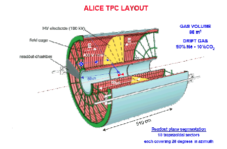
The TPC is cylindrical in shape with an active gas volume that ranges from about 85 cm to 250 cm, in the radial direction, and has a length of 500 cm. along the beam direction. A high voltage (HV) electrode is located at its axial center, which will be aligned to the interaction point, dividing the gas volume in two symmetric drift regions of 250 cm length. The HV electrode, which consists of an aluminized stretched Mylar foil, and two opposite axial potential degraders create a highly uniform electrostatic field in the two drift regions. The potential of the drift region is defined by Mylar strips wound around 18 inner and outer support rods.
Charged particles traversing the gas will leave behind the memory of their passage in the form of a long trace of ionized gas. Depending on the electrical charge and momentum of the particle the trace will be bent weaker or stronger in either direction. In addition the density of the ionization depends on the momentum and identity of the particle. The ionization trace moves at constant velocity to either of the two end plates. The end plates are equipped with wire planes and 560,000 electronics channels, detecting the fundamental properties of the ionization trace (3D image and ionization density). The requirements of good momentum resolution and high rate capability call for a drift gas with low diffusion, low Z and large ion mobility. Extensive investigation of different gas mixtures led originally to the choice of the mixture 90% Ne-10% CO2. More recently it was proposed to add 5% N 2 to the mixture, which turned out to provide, higher gas gain stability and a better control of the fraction of N2 and its influence on the drift velocity. Both gas mixtures, however, require a high drift field (400 V/cm) to secure an acceptable drift time (88ms and 92ms respectively). The field cage is surrounded by double-shelled containment vessels with CO2 as insulator. Composite materials based on carbon fibber were chosen for high mechanical stability and low material budget (only 3.5% of a radiation length for tracks with normal incidence).
The TPC end-plates are each segmented into 18 trapezoidal sectors and equipped with multi-wire proportional chambers with cathode pad readout covering an overall active area of 32.5 m2. The sectors are segmented radially in two chambers with varying pad sizes, optimized for the radial dependence of the track density. There are about 560 000 pads with 3 different sizes: 4 for the inner readout chambers (IROC), 6 x 10 and 6 x 15 mm2 for the outer chambers (OROC), with 159 pad rows radially. For a position resolution not limited by the signal-to-noise ratio, the gas gain has to be sufficiently large. For the chosen pad sizes and rather low dE/dx of the drift gas, a rather large gas gain of 2 104 is necessary at the design noise figure of 1000 e (rms) for the electronics.
The charge collected on the TPC pads is amplified and integrated by a low input impedance charge sensitive amplifier followed by a semi-Gaussian pulse shaper. These analogue functions are realised by a custom integrated circuit (PASA), implemented in a 0.35 mm CMOS technology, which incorporate 16 channels. The circuit has a conversion gain of 12mV/fC, an impulse response function with a peaking time of 150ns and an equivalent noise charge of about 600 e- . Immediately after the PASA, a 10-bit pipelined ADC (one per channel) samples the signal at a rate in the range 5 to 12 MHz. The digitised signal is then processed by a set of circuits that perform the baseline subtraction, tail cancellation, zero-suppression, formatting and multi-event acquisition. The ADC and the digital circuits for 16 channels are contained in a single custom chip, named ALTRO, implemented in a 0.25 m m CMOS technology. The complete readout chain, which has a power consumption of about 40 mW / channel, is contained in Front End Cards (FEC), with 128 channels each, connected to the detector via kapton cables. A readout partition consists of a number of FECs (up to 25), which are controlled by a Readout Control Unit (RCU). The RCU interfaces a readout partition to the Data Acquisition (DAQ), the Trigger, and the Detector Control System (DCS). Every TPC sector (15488 channels) is readout by 6 partitions (121 FECs).
Click here to access the paper "The ALICE TPC, a large 3-dimensional tracking device with fast readout for ultra-highmultiplicity events", submitted to Nuclear Instruments and Methods in Physics Research Section A