The TPC is essentially a 90 cubic meter volume filled with gas, where the gas is the detecting medium. The detector performance depends crucially on the gas choice, stability and quality, since these influence the charge transport in the drift volume and the amplification processes in the readout chambers. The choice of the gas composition is constrained by a set of performance requirements and boundary conditions, and in turn the selected gas mixture determines the performance of the detector and conditions various aspects of its design, from the shaping time of the front-end electronics to the temperature uniformity of the gas in the detector. In particular, the gas system is designed to fulfill the requirements derived from the gas choice and the expected performance of the detector.
The selection of both the noble gas and the quencher was made by a process of elimination rather than choosing the gas by its merits. Between Ar and Ne, the former, although providing larger primary statistics, was discarded because of material-budget considerations and a slow ion mobility. In particular, Argon would substantially enhance space-charge effects in the drift volume of the TPC due to its relatively slow ion drift velocity. As far as the quencher is concerned, hydrocarbons were excluded due to ageing considerations (Malter currents would set in after about 1 year of operation with heavy-ion beams). CF4, on the other hand, presented many concerns with material compatibility at the time of the system design. Therefore, CO2 was chosen. Since the maximum drift field in the field cage was designed to be 400 V/cm, and the maximum drift time 90 microseconds, the composition results in 10% CO2 in Ne. During the prototyping phase, a further 5% of N2 was added to the mixture. This addition reduces the drift velocity at the nominal field by about 5%, but it provides a more stable operation of the readout chambers at high gain. This also eliminates the problem that N2 could build up in the gas due to small leaks. The changing nitrogen content would then affect the detector performance since it cannot be removed by the cleaning agents of the gas system. Excited states of neon have energies around 17 eV, for which the quenching capabilities of CO2 are poor. More CO2 in the mixture would rapidly decrease the drift velocity. N2, on the other hand, presents a slightly higher ionization cross section at these energies and so helps to quench the Ne, and affects the drift velocity modestly. The resulting mixture is also less sensitive to the exact composition. The slow proton production due to neutron bombardment of N2 molecules has been shown in simulations to be reasonably small. The main implication of the choice of a NeCO2N2 gas mixture for the gas system is the necessity of monitoring and controlling a ternary mixture.
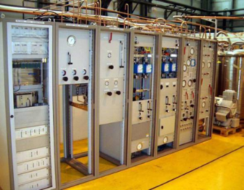
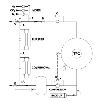 Most of the gas systems and control programs of the LHC experiments are designed and built under a common modular scheme coordinated by CERN infrastructure groups. Each function of the gas system, such as the gas mixing, the circulation, the cleaning, the analysis, etc., is integrated into a logical module which usually corresponds to one or more racks. A Programmable Logic Controller (PLC) runs the system by executing actions, like opening a valve, or a sequence of actions, regulating devices according to set points, like flows or pressures, reacting to alarms, reading analog and digital values, including Profibus networks, and publishing information to a user interface. The user interface allows the operator to change the state of the gas system, for example from fill to run states, and to act on individual modules or on single components of the system. It also logs the various data points into a data base for inspection of trends. A set of recipes, or configuration files, specific for each module, is loaded into the PLC for determination of set points, limits, regulation parameters, timers, etc., which the operator can edit and reload at any time from the user interface. The racks are distributed in a surface building, in the plug of the shaft (a shielded platform just above the cavern), and in the cavern, according to their functions and specifications. The gas system is a gas circulation loop with injection, distribution, regulation and other tasks distributed in modules located at different elevations in the ALICE hall. Gas is circulated through the detector by a compressor module, which extracts the gas from the TPC and fills a high-pressure buffer volume for gas storage. A regulated bypass proportional valve re-injects part of the compressed gas back into the compressor inlet, as part of a feedback loop to regulate the pressure inside the TPC. This valve is driven by a pressure sensor installed at the detector. which determines the operating pressure set point with respect to atmosphere. The TPC overpressure is thus regulated to 0.4 mbar. The high-pressure buffer, a 1m3 tank at 2-4 bar overpressure, stores gas that can be delivered to the detector in case of an increase of the atmospheric pressure, or can accept gas from the detector when the ambient pressure decreases. Once at a few bars overpressure, the gas, depending on the system mode, flows through several modules, located on the surface, or is directly vented out through a back-pressure regulator (V) if the detector is being flushed with CO2 (purge mode). The purifier, CO2 absorber, the exhaust, the analysis and the mixer modules are installed on the surface. The mixer can be programmed to inject a fixed amount of fresh gas into the loop. Part of the excess gas in the system is exhausted through the analysis lines (A). The remainder of the excess gas in the loop is exhausted through a mass-flow controller (E) regulated against the pressure set-point in the high-pressure buffer. In run mode, the Cu-catalyzer purifier is activated, so that one of its two cartridges continuously removes O2 and H2O from the gas. These cartridges can be regenerated on the spot by a programmed sequence of purging them with hydrogenated gas and heating them. After the gas injection from the mixer into the gas loop, the pressure is decreased to a fraction of a bar by a high-precision needle valve (D). The resulting pressure will determine the total gas flow (from surface to cavern) through the detector, whose pressure is fixed by the compressor module. This configuration allow for independent settings of the detector pressure and the gas flow, a feature of closed-loop gas systems.
Click here for the homepage of the CERN Gas Working Group.