 Large-scale TPCs have been employed and proven to work in collider experiments before, but none of them had to cope with the particle densities and rates anticipated for the ALICE experiment. For the design of the Read-Out Chambers (ROCs), this leads to requirements that go beyond an optimization in terms of momentum and dE/dx resolution. In particular, the optimization of rate capability in a high-track density environment has been the key input for the design considerations. The ALICE TPC has adopted MWPCs with cathode pad readout.
The azimuthal segmentation of the readout plane is common with the subsequent ALICE detectors TRD and TOF, i.e. 18 trapezoidal sectors, each covering 20 degree in azimuth. The radial dependence of the track density leads to different requirements for the readout-chamber design as a function of radius. Consequently, there are two different types of readout chambers, leading to a radial segmentation of the readout plane into Inner and Outer ReadOut Chamber (IROC and OROC, respectively). In addition, this segmentation eases the assembly and handling of the chambers as compared to a single large one, covering the full radial extension of the TPC.
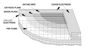
The ALICE-TPC readout chambers employ a commonly used scheme of wire planes, i.e. a grid of anode wires above the pad plane, a cathode-wire grid, and a gating grid. All wires run in the azimuthal direction. Since the design constraints are different for the inner and outer chambers, their wire geometry is different. The gap between the anode-wire grid and the pad plane is 3 mm for the outer chambers, and only 2 mm for the inner chambers. The same is true for the distance between the anode-wire grid and the cathode-wire grid. The gating grid is located 3 mm above the cathode-wire grid in both types of chamber. The anode-wire grid and the gating grid are staggered with respect to the cathode-wire grid.
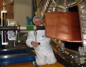
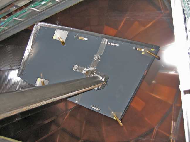
The chambers are attached to the endplate from the inside to minimize dead space between neighboring chambers. This required a special mounting technique, by which the chambers are attached to a long manipulator arm, which allows the rotation and tilting of the chambers. This mounting technology had already been used by the ALEPH collaboration, from which we inherited the manipulator device. The chambers, attached to the tip of the manipulator arm, are first adjusted in angles such that they can be moved through the endplate , thereafter they are turned and retracted into their final position.